Single-phase asynchronous electric motors with short-circuit cage of closed design
Single-phase asynchronous electric motors with short-circuit cage of closed design, power up to 2.2 KW
Description
Data from single-phase electric motors with a short-circuit cage for the power range from 0.045 kW to 2.2 kW are described. The installation dimensions are in accordance with the recommendations of IEC publication 60072. The electric motors comply with DIN VDE 0530 T1.
Mechanical design
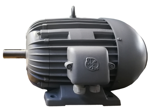
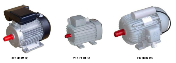
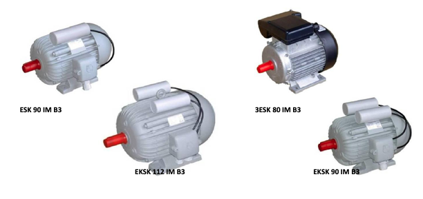
Single-phase electric motors are similar in design to three-phase IEC electric motors. The normal design is IM B3 and the protection level is IP 54. The capacitors are attached to the top of the stator housing with special clamps and connected to the terminal block in the cabinet. Automatic thermal protection switches and thermal sensors are built into the windings of electric motors. Electric motors (3) ESK and (3) EKSK have a built-in centrifugal switch in the bearing shield on the N side.
One or more capacitors are mounted on single-phase electric motors. Single-phase electric motors have the same bearings as three-phase electric motors of the same size, except for electric motors with a starting capacitor (EKSK 100 and EKSK 112), where 6205 2Z bearings are installed on the N side.
Electrical version
Rated power
The powers given in the tables are the rated powers emitted by the electric motors on the shafts at constant load, at rated voltage and frequency, at an ambient temperature not exceeding 40°C and at an altitude of up to 1,000m.
Change of power
The power of the electric motor may decrease or increase if the following operating conditions are changed:
1. if the mains voltage or frequency changes by more than ± 6%
2. if the cooling conditions change
3. if electric motors are operated at a special drive
4. if the electric motors must comply with regulations other than IEC 60034 or DIN VDE 0530 T1.
Voltage and frequency
Standard electric motors are electric motors built for connection to the 230V, 50Hz network. Upon special request, we can also produce electric motors for other voltages and frequencies.
Performances
Depending on the implementation of the auxiliary phase, we divide single-phase electric motors into:
a.) single-phase electric motors with a permanently connected, i.e. drive capacitor
b.) single-phase electric motors with starting capacitor
c.) single-phase electric motors with starting and drive capacitors.
Thermal protection
Single-phase electric motors can also be protected by users themselves with circuit breakers (see page 10). At the request of customers, we install the following in electric motors:
1. Automatic thermal protection (bimetal in the winding of the electric motor) – mark A
2. Electronic thermal protection (thermistor in the winding of the electric motor) – mark E
Electronic thermal protection represents complete protection of the electric motor because it reacts in the following cases:
1. Short circuit (electric motor screw)
2. Starting too heavy (electric motor is overloaded)
3. Overload (electric motor is overloaded)
4. Too low or too high mains voltage or frequency
5. Insufficient ventilation (blocked flow or too high temperature of cooling air, etc.)
Automatic thermal protection with a bimetallic switch in the motor winding in the event of a short circuit and too heavy a start is not the most effective due to the slow response. Automatic thermal protection switches can be connected to the winding circuit for lower power motors, and contactors must be additionally attached for higher power.
The thermal protection switch with automatic restart only restarts the electric motor after it has cooled down. These switches may only be used where safety regulations allow. Their use is not permitted in electric motors that drive machines and devices where the immediate and unexpected restart of the electric motor can cause personal injury to the user (e.g. circular saws, carpentry machines, grinding machines, etc.). Automatic thermal protection (bimetal in the winding of the electric motor) automatically restarts the electric motor (up to the size of 80, bimetal directly switches the electric motor on and off, while for larger types additional switching devices-contactors are required). In the case of electronic thermal protection, the switch-off electronics can be adapted for automatic or manual restart.
Thermal circuit breakers are determined in accordance with IEC 60034-11. Automatic thermal protection switches can be directly connected to the winding circuit for lower power motors, while contactors must be additionally attached for higher power.
Operating data of single – phase asynchronous electric motors
Standard voltage: 230V, frequency: 50Hz.
Electric motors with drive capacitor
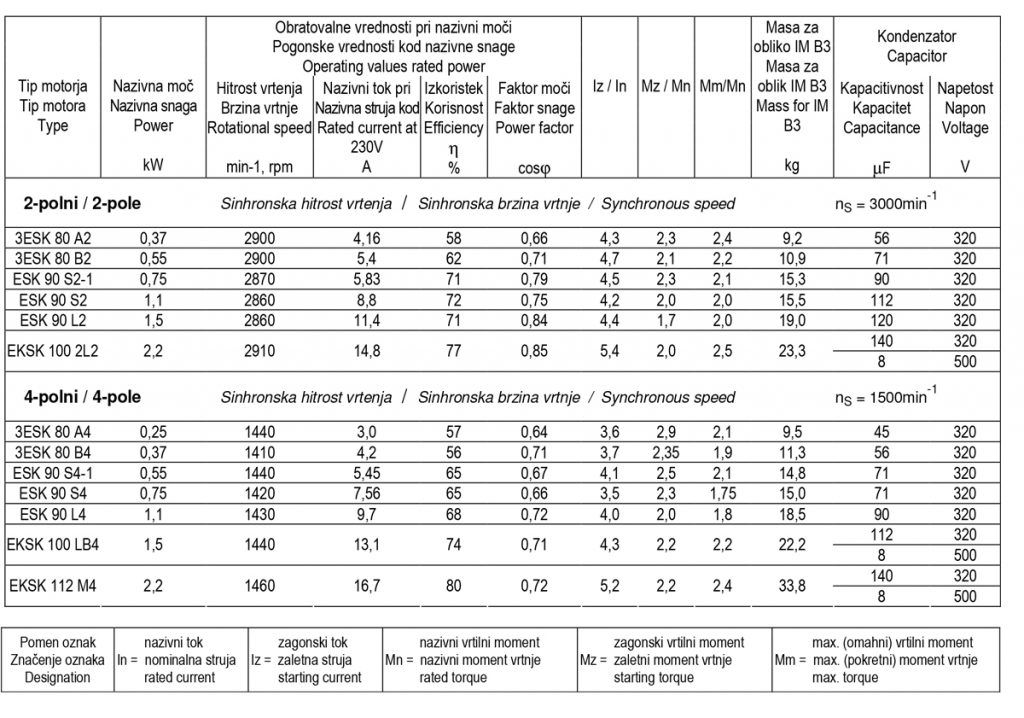
Operating data of single - phase asynchronous electric motors
Standard voltage: 230V, frequency: 50Hz.
Electric motors with starting capacitor and electric motors with starting and driving capacitor
Start with centrifugal switch.

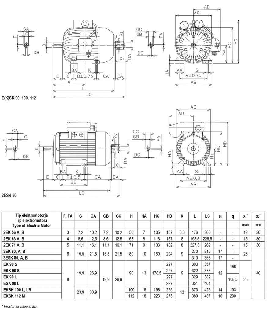
Dimensions of single-phase asynchronous electric motors
Electric motors with drive capacitor in auxiliary phase.
Foot design: IM B3 (IM B6, IM B7, IM B8, IM V5, IM V6)
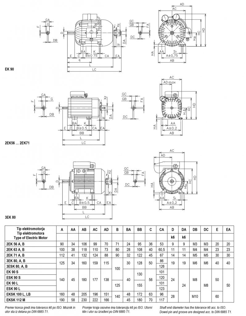
Dimensions of single-phase asynchronous electric motors
Electric motors with starting capacitor and electric motors with starting and drive capacitor and with centrifugal switch in auxiliary phase.
Foot design: IM B3 (IM B6, IM B7, IM B8, IM V5, IM V6)
